Cast Iron Pipe Gravity Flow Rate Calculator
Introduction to Cast Iron Pipes
Cast iron pipes have been widely used in plumbing and construction for centuries due to their durability, strength, and resistance to wear and tear. They are commonly used for drainage systems, sewer lines, and water mains. Below, we explore the properties, uses, and advantages of cast iron pipes.
Properties of Cast Iron Pipes
- Durability: Cast iron pipes are highly durable and can last for decades, even under harsh conditions.
- Strength: They have high tensile strength, making them resistant to cracking and breaking.
- Corrosion Resistance: Cast iron pipes are resistant to corrosion, especially when coated with protective materials.
- Sound Insulation: They provide excellent sound insulation, reducing noise from water flow.
- Fire Resistance: Cast iron is non-combustible, making it a safe choice for fire-prone areas.
Uses of Cast Iron Pipes
- Drainage Systems: Commonly used in residential and commercial drainage systems.
- Sewer Lines: Ideal for sewer lines due to their durability and resistance to corrosion.
- Water Mains: Used in municipal water supply systems.
- Stormwater Systems: Effective in managing stormwater runoff.
- Industrial Applications: Used in industrial settings for waste disposal and chemical transport.
Advantages of Cast Iron Pipes
- Long Lifespan: Can last over 100 years with proper maintenance.
- Low Maintenance: Requires minimal maintenance compared to other materials.
- Eco-Friendly: Recyclable and environmentally friendly.
- Noise Reduction: Reduces water flow noise, making it ideal for residential buildings.
- High Load-Bearing Capacity: Suitable for heavy-duty applications.
Material Roughness Coefficients
| Material |
Roughness Coefficient |
| Cast Iron |
100 |
| Concrete |
110 |
| Copper |
140 |
| Plastic |
150 |
| Steel |
120 |
Velocity of Water Flow in a Pipe: An Example
Let’s use the pipe flow calculator to determine the velocity and discharge of a plastic pipe with a diameter of 0.6 feet. The pipe is 15 feet long, and the height difference between the beginning and endpoints is 6 feet.
Step-by-Step Calculation:
1. Calculate the Radius of the Pipe
Divide the diameter by 2 to find the radius:
\[ r = \frac{d}{2} = \frac{0.6}{2} = 0.3 \, \text{ft} \]
2. Find the Cross-Sectional Area of the Pipe
Use the formula for the area of a circle:
\[ A = \pi r^2 = \pi \times 0.3^2 \approx 0.2827 \, \text{ft}^2 \]
3. Determine the Perimeter of the Pipe
Calculate the perimeter using the formula:
\[ P = 2 \pi r = 2 \pi \times 0.3 \approx 1.885 \, \text{ft} \]
4. Calculate the Hydraulic Radius
Divide the area by the perimeter:
\[ R = \frac{A}{P} = \frac{0.2827}{1.885} \approx 0.15 \, \text{ft} \]
5. Select the Roughness Coefficient
Choose "Plastic" from the drop-down list, which has a roughness coefficient of:
\[ C = 150 \]
6. Calculate the Slope of the Pipe
Divide the height difference by the length of the pipe:
\[ S = \frac{y}{L} = \frac{6}{15} = 0.4 \]
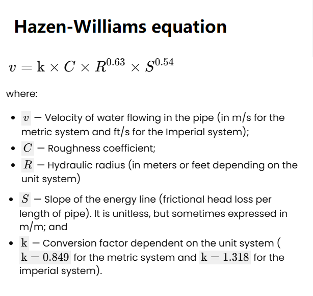
7. Use the Hazen-Williams Equation to Find Velocity
Apply the Hazen-Williams formula:
\[ v = 1.318 \times C \times R^{0.63} \times S^{0.54} \]
\[ v = 1.318 \times 150 \times 0.15^{0.63} \times 0.4^{0.54} \approx 36.48 \, \text{ft/s} \]
8. Calculate the Discharge
Multiply the velocity by the cross-sectional area:
\[ Q = A \times v = 0.2827 \times 34.56 \approx 10.31 \, \text{ft}^3/\text{s} \]
Flow Rate Calculator© - All Rights Reserved 2025
 Home
Home Back
Back